FURNACE COMBUSTION CONTROL
Executive Summary:
A new control system was needed for the melting and holding furnaces at a casting operation. The old one had been destroyed by fire and so the design-build cycle was compressed to weeks. The old controls were of limited use in determining the control strategy and sequence of operation. Research on furnace combustion was conducted and a cascade PID control loop strategy was found in a research paper and adapted to this project. Kredit Automation is experienced in process control and PID loop programming and quickly designed a program to leverage the combustion strategy. In less than a month the plant was melting and casting again, in full production.
Project Details:
A fire consumed the control room and control systems for both furnaces. Fortunately no one got hurt but the control panels and operator stations were obliterated and production ceased. Fortunately, the two furnaces themselves were not severely damaged and could be run after some repairs to valves and other instruments—but only after a complete new control system was created and a complete rewire was done. A new gas train was also needed on one furnace.
Kredit began the project the same day as the fire. A new panel was designed and produced with a ControlLogix L71S safety controller. A survey of available papers and textbooks was done to locate helpful information on a control strategy. An innovative cascade PID control strategy was discovered that had been done on similar furnaces and which could be adapted for these furnaces. The ControlLogix programming for this combustion control was written. New operator interfaces with graphic screens were created in a Rockwell PanelView Plus operator station. The system was completely rewired and new air and gas valves installed along with new instruments.
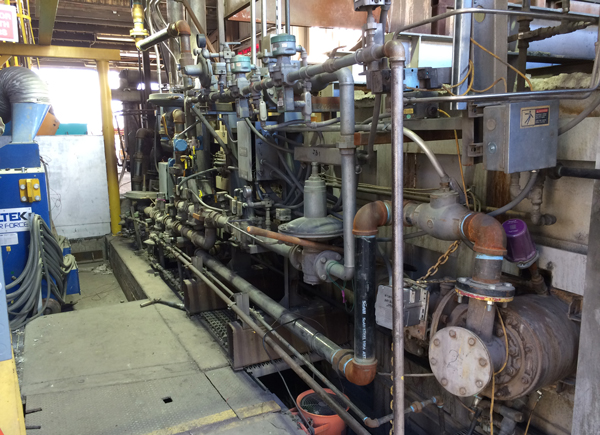
The melting furnace is where large aluminum ingots as well as various types of scrap aluminum are melted down. The holding furnace is where the molten aluminum is buffered and maintained at temperature next to the cast pit. The melting furnace is shown in the figure as it actually appeared at the start of the first melt under the new control system.
The theory of operation of the melting furnace is interesting. The temperature of the bath of molten metal is maintained by a feedback control loop whose output adjusts the setpoint of another feedback control loop that controls the temperature of the upper furnace (which is called the roof temperature). In other words, the bath temperature loop works by adjusting the roof temperature. This is a classic cascade control loop with the bath temperature being the outer loop and the roof temperature being the inner loop. The roof temperature loop in turn regulates the roof temperature by adjusting the setpoint to the air flow controller. In other words the roof temperature works by adjusting the air flow. This is also a cascade control loop with the roof temperature being the outer loop and the air flow being the inner loop. Since both components of this cascade loop are the inner loop of the bath loop, we actually have a triple cascade control loop as the core control strategy of the combustion control. The gas flow loop is ratio’d off the air flow loop to maintain the air to gas ratio. The diagram below is a simplified representation because all the scaling, tracking, manual control, and local setpoint control logic has been removed to make it more readable. This is diagram is actually taken from the function block routine in the ControlLogix program.
Another interesting thing about the melting furnace is the burners are alternated. Some of the hot exhaust air from the furnace is directed in the reverse direction past the entrance to the inactive burner to preheat the ceramic bed at the inlet. Alternating the burners and preheating the inlets increases efficiency and improves emissions compliance. This requires a precise sequencing logic routine that is synchronized with the rest of the continuous combustion control logic routines and PID loops.
The program was fully parameterized (no hard coded values or settings) and included all modes of operation. This means the loops could be run in local setpoint control, manual control, or full auto. Full auto means the setpoints of the two inner loops (roof and air) come from the output of the loop above them in the cascade (bath and roof). Local setpoint control means one of the setpoints is in auto but is in local mode and its setpoint is entered by an operator instead of being a scaled multiple of the output of the loop above it in the cascade. For example, the operators often prefer to run the roof temperature control loop in local setpoint. This means instead of the setpoint being a scaled multiple of the output of the bath loop, the operator directly enters the desired setpoint of the roof temperature. The air and gas loops are in full auto and the setpoint still comes in as a remote setpoint from the output of the roof temperature control loop.
There are other interesting challenges to report. As one might expect, a lot of issues arose around wiring and instrumentation. Kredit Automation gradually took a lead role in supervising and helping with a lot of the work needed to get these systems running again. This was not initially forecast but became a necessity and was well received by the grateful customer.

