ROBOTIC INTEGRATION & END OF ARM TOOLING DESIGN
Executive Summary:
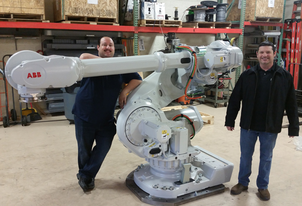
Kredit Automation and Controls completely retrofitted the controls on a system that produces molds for casting. The customer manufactures turbine engine components. The old control system was a functional but aging system based on a Vulcan Engineering Electrobot robot, an Allen-Bradley SLC-500 PLC, and a Visual Basic program. The old system had almost all the sequential logic in the Visual Basic Program. The new control system features a new ABB IRB7600 Foundry Plus 2 robot and a ControlLogix PLC and FactoryTalk HMI. The new robot is faster, more accurate, and easier to program. The new PLC contains all the sequential logic program and robot commands. It is modular, structured, commented and designed to be straightforward to work on and upgrade for years. The opportunity was also taken to make significant improvements to the sequence, the ease of robot use, and the operator interface.
Project Details:
The process of making a mold starts by making a dimensionally exact wax replica of the part to be cast. At this plant a typical part is a turbine blade. A group of wax replicas and final production parts are shown in the figure. (The two sides don’t show the exact same parts but the idea is conveyed).
Next a mold is produced by a shelling process, which is what this control system and robot control. The shelling process puts a series of coats on the wax replica. These coats are made of slurry and ceramic sand. Then the wax is melted out and the remaining shell is now a mold. (The melt out of the wax replica to yield the mold is where the name “lost wax” comes from.) The actual production part is then produced by a casting process using the mold.
The lost wax process consists of a series of “dips”. A dip is the application of slurry and sand followed by a drying time. A typical mold gets about 6-10 dips. The slurry is a highly engineered material that penetrates every nook and cranny of the surface and adheres closely. The robot dips the mold in a slurry tank as it turns and rotates the mold to get a coverage that is as even and complete as possible. The robot then lifts the mold out of the slurry tank and rotates the mold around over the tank to let slurry drip off and further even out the coverage. Next, the robot takes the mold into a rotating drum called a rainfall sander. Ceramic sand is gently and evenly poured over the mold as the drum rotates. As the rainfall sander rotates the robot moves the mold around over a wide range of angles to achieve as even a coverage of the sand on the slurry layer as possible. The sand adheres tightly to the slurry. This layer is dried in a drying tunnel under carefully controlled environmental conditions for 2-6 hours. Then six to ten more dips are performed. There are seven different slurries and four different sands. A recipe specifies which slurry and which sand is used for a given dip as well as the dry time. After the last dip and the final drying the shelling process is complete. Downstream in another section of the plant the wax is melted out in a furnace and the remaining mold undergoes some final prep to get it ready to use in the casting process.
Programming the old robot had always been difficult for the customer. The robot operating system was an early vintage. The user application program was not the friendliest in terms of end user modification and expansion. The net effect was that modifying or adding profiles was a chore. A profile in this application is the series of moves inside or above a slurry tank or rainfall sander. The new robot program was designed to significantly improve the user experience over the previous robot. The modern operating system and an application program designed with the end user in mind make configuring profiles a much more straightforward task. One of the most vexing problems with the old system is that it would get stuck or crash or if someone hit an estop and the only way to recover was to cycle power to the entire system, re-home the robot and start everything over. The progress of the molds was lost which required re-entering a lot of information in such a way as to artificially progress to where they had been. This required a lot of effort, was subject to errors, and caused large amounts of downtime. The new system can recover from such problems without nearly the headaches or effort. The new system has also been programmed with cycle pause and immediate robot pause features, neither of which cause any issues and can be used and then removed for an error-free mold sequence restart. Because of the improved interface to the robot additional information such as the level of the slurry tanks (measured with newly installed laser sensors) can be sent to the robot where the dip profile can be adjusted accordingly.
The old robot had more linear actuators and fewer servos than the new robot. Some of the mechanical linkages had developed enough wear to cause significant accuracy problems. This required lowering the speed of robot actions. Even with slower speed mishaps such as missing a hook were starting to occur more frequently. Sometimes the old robot would have problems to the point of actually damaging the molds, which was a very expensive problem. As one would expect, the new robot was extremely accurate even at much greater speed.
The old system had the main program written in Visual Basic. All the sequential logic and robot commands were in the VB program. The new control system placed the sequential logic and robot interaction in ladder logic in the ControlLogix PLC. This code is modular, structured, commented, and designed to be accessible to programmers needing to make modifications and additions. The fact that the core control is in a ControlLogix guarantees upgrades will be straightforward for many years.
This project succeeded in the primary goals of modernizing the equipment and thereby addressing maintenance and obsolescence concerns. But the opportunity to improve the control algorithms and operator interfaces were also of great value to the customer. The new robot’s accuracy and superior programming interfaces caused the project results to exceed expectations. One of Kredit Automation’s mechanical engineers designed an innovative end-effector that was much improved over the previous one. A special 60” pedestal of high strength, high stiffness steel was engineered to allow the new robot to reach all the existing points that the old robot did, facilitating a more compact and efficient robot motion system. In addition, most of the programming and robot commissioning was done ahead of time at Kredit Automation’s facility to reduce the amount of customer downtime during installation and start up. The time to remove the old robot, install the new robot, install the new control panel, rewire the entire system, do an I/O checkout and debug logic to the point of running molds was only two weeks.
Custom DCS to Air Handling Unit Communication Box
Kredit Automation & Controls together with the 508 panel shop, designed and built a custom communication interface box complete with a Kredit Automation & Controls designed circuit board. This box handles all communications from the data cent air handling units (AHU) to the DCS SCADA system.
4 Axis Wire Winding Machine Controls Retro Fit
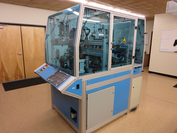
The purpose of this retrofit was to offer the opportunity to trouble shoot the machine at the mechanical/electrical interface level. We were able to get to the point of transparency at that level, and improve functionality of the machine by eliminating some poor programming practice in the Motion-Control/PC programming that stops sequences to wait for completion of other sequences when instead these could be overlapped.
In addition, by applying currently available PLC technology to this retrofit, we will make the system available to troubleshooting minor components, such as Proximity sensors. Recipe structure selection was moved from the local PC to the Panel View Plus. With the upgraded PLC we were able to move the motion controls inside of the PLC, simplifying the communications greatly. In addition the new PLC can accept analog inputs directly which increased the speed of communication between the controller and the drives.
- Replaced existing computer and HMI with Allen Bradley Panel View Plus
- Replaced obsolete control system and replaced with new Allen Bradley Compact Logic platform
- Replaced obsolete motion controller with new Baldor NextMove
- Removed CanBus communications in favor of direct I/O
- Replaced old Bus I/O with Allen Bradley Flex I/O for ethernet communications
Cooling Tower Controls Installation
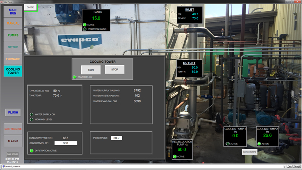
Installation of cooling tower instruments and controls. Control Panel built in our UL508A industrial control panel shop.
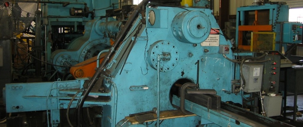
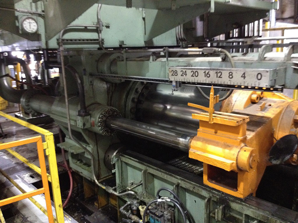
1500 Ton Aluminum Extrusion Press
Customer: Alexco
Machine: 5″, 1500 Ton Sutton Aluminum Extrusion Press
Work completed:
• New hydraulic manifolds to eliminate hydraulic leaks and valve failures
• New, original press control PLC programming, with precise ram feedback and advanced PID feedback loop
• New touch screen display replaced extrusion press push buttons and thumb wheel
Results:
• Significantly reduced extrusion press downtime
• Higher quality extrusions
• Reduced setup and training time
• Decreased dead cycle
PRINTING BARCODES DIRECTLY FROM A PLC PROGRAM
Executive Summary:
The L-Shear uses servos to position large laminated copper sheets under a shear to cut them into precise sizes used for circuit boards. One goal of a recent control system retrofit was to allow bar code printing to be controlled by a PLC without requiring a computer or operator data entry. This machine is a limiting factor in plant production speed. This meant that plant production was impacted when data entry errors necessitated a special re-run through the L-Shear to reprint. The ability to print a barcode while the sheet is in motion and the reduction in scrap and rework due to data entry errors was a key accomplishment of the retrofit.
Project Details:
The machine is called an L-Shear because two conveyors have their ends aligned at a right angle. Large laminated sheets go down the first conveyor and are trimmed into several sections by a shear. Then when each of those trim sections reaches the backstop of the first conveyor they are lifted onto and run down the second conveyor where each is cut several times to produce the final sections.
The previous control system was a proprietary black box. Making changes required contacting an engineer in Holland which was expensive and inefficient. Integration with the rest of the plant and integration of new components such as a printer were difficult. Additional concerns about parts and obsolescence convinced management to upgrade to commercial off the shelf controls. This provided an opportunity to rewrite the program and redesign the operator interface to accommodate ideas for improvement and new features such as an integrated recipe management system. Allen-Bradley Kinetix servos were used to achieve even greater accuracy. The new system was very successful in all regards. The new program is well structured, well commented ladder logic. It was designed from the start to be amenable to modifications, additions, and integration with other systems.
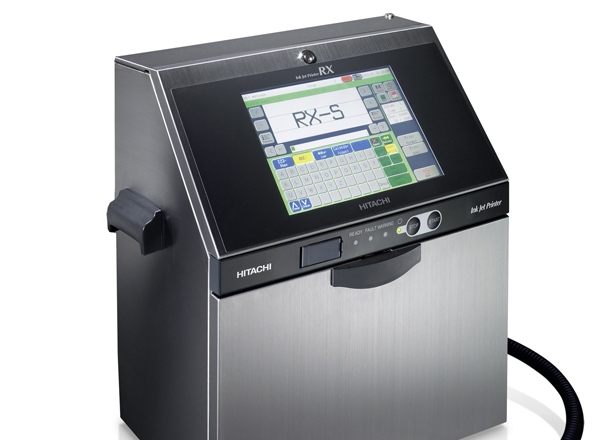
This capability to integrate was first put to use and proven successful when an inkjet printer was easily added to the system. The owner wanted fast printing speed so that no slowdown of the line would be needed. The owner also wanted the printer run by the PLC with no operator involvement or data entry. The new controls featured a ControlLogix processor with EtherNet/IP and so connecting an industrial printer was simple. We just added a profile in the PLC program and got a tag structure ready to use to write PLC logic to print barcodes.
The previous printer could not be integrated and required a separate computer. At this company having to use a PC meant the IT group was involved. This windows PC had to be maintained. The printer was not really integrated because hardwired I/O and completely custom logic and interfaces were needed. The line had to run a little slower to print acceptably. But the worst thing about the old system was that the print information had to be entered manually by an operator. Mistakes and rework were common. Not only did this require time by the operators but also required running it through the L-Shear again…a double hit on productivity.
The new inkjet printer assembly includes an encoder that measures conveyor speed. This enables the printer to spray on a highly accurate and durable bar code with no physical contact and no slowdown requirement. Because the new inkjet printer has predefined tags ready to use in PLC logic, the PLC program incorporates order and production about the part into the barcode and sends it directly to the printer and controls the exact printing sequence. This feature is a significant time and money saver and is much appreciated by the operators and management.
Sapa Extrusion Press Control System Upgrade
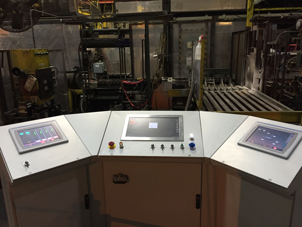
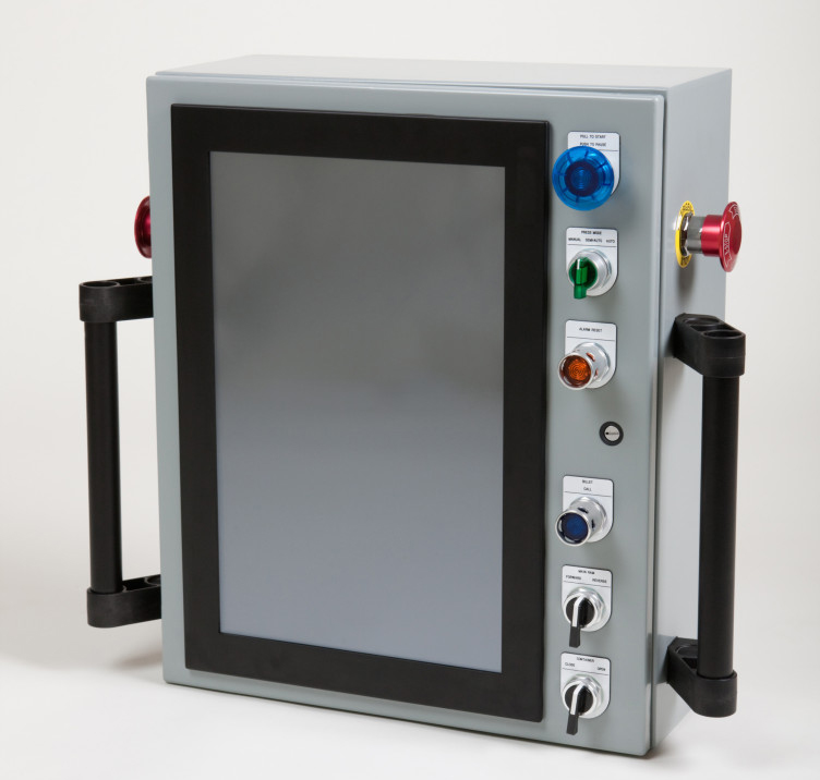
Vertically mounted HMI: Narrow Operator Station allowing for easier visibility on both sides of screen, with a high amount of real estate available on screen.
TUBE AND CONDUIT MATERIAL HANDLING AND BUNDLING
Executive Summary:
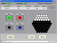
Kredit Automation was contracted to retrofit the PLC and HMI on a line that bundles tubes coming off the fabrication line. (Tubes are made by roll forming cut-to-length steel sections into a tube and welding the seam. Various chemical treatment and coating steps including intense UV irradiation result in tubes fit for various harsh conditions and duty.) This project was done to replace aging equipment for which reliability and parts availability and a closed proprietary HMI were increasing concerns. Those goals were accomplished and the customer was further pleased by the usability of the new program for the line in the other mill.
Project Details
Tube bundling sounds mundane but when a single line is responsible for handling different tube sizes and producing bundles of varying geometry (and doing so at a consistently rapid rate) the control challenges are more subtle than they first appear. There is more I/O—several hundred points—than one might imagine. A fairly large and fast PLC is needed to run this line.
The customer was concerned that the PLC (an older model from a reputable European company) was aging and that software and spare parts were becoming an increasing concern and risk. The operator interface was of particular concern because it was non-COTS and was a complete black box. They had just one spare and the spare didn’t have the very latest program. There was no way to duplicate the HMI or upgrade the program in the spare. The decision the customer had to make was between converting the program to the European company’s latest PLC and creating a completely new HMI or switching to a Rockwell (Allen-Bradley) PLC and HMI. While the former approach would have been feasible, the Rockwell direction was chosen by this customer. Their plant was standardized on the SLC-500 family so the Ethernet-based SLC-5 was used along with FactoryTalk View SE for the HMI.
Constraints regarding the geometry of the bundles (e.g. square vs. hexagonal) and other matters were analyzed and it was realized that these constraints could be effectively handled with classic database design. Microsoft Access was used (part of the Microsoft Office product). Changes and modifications could be accomplished much more easily using Access than having to modify PLC code and HMI screens. The figure below shows how the table relationship tool in Access provides an intuitive visual design tool that enables these relationships to be set up to the meet the requirements. Trying to do this in PLC code would be much more complex and hard to modify. And since it is Microsoft Office it is a COTS component.
Because both FactoryTalk SE and Access use VBA as their macro language, Visual Basic code was used to set up a system whereby the HMI screens and Access forms were part of one unified HMI, both of which communicate with the PLC. The database was a recipe and order system that was simple and integrated into the control system. It is emphasized that this system can be duplicated simply by installing FactoryTalk and Office…no customization of the PC whatsoever is required. Just loading the software and placing the application files on the new computer will allow it to run out of the box.
The PLC program was structured and commented to make it amenable to being modified and upgraded. An upgrade to the Logix family is planned for next year. Modular design techniques—a KAC specialty—made it possible to reuse large parts of this program on another tube line in the plant. The lines were different enough that an ordinary program would have required extensive work and probably ended up a kludge but by carefully structuring the program it was possible to reuse modules as-is and create another clean program for the other mill.
Because the old prints and documentation were incomplete and in a foreign language, and because the program was in an arcane assembly language format with no tags or descriptors, KAC applied an innovative technique to study the behavior of the program. First the I/O was compiled and translated to a point where a decent I/O list existed. Then the I/O cards were videotaped at high speed while the line ran. The patterns and behavior of the LED lights were studied to ascertain basic things about the sequences. Then the program was written using this insight. While this was very tedious and time consuming, it allowed the project to move forward.
As is standard practice in these types of projects, KAC omitted any obsolete or unused aspects or features or equipment from the line when designing the new program and operator interface screens. Only the equipment and process steps that would be used going forward were included. While this was most of the original system, it did allow some trimming and cleanup to take place from the standpoint of the customer. In particular, the HMI (including the integrated database entry and selection forms) were much better suited for their needs than the old HMI, not to mention larger, clearer and more user-friendly. The customer gained a COTS system with a new, well-structured, highly commented program and a dramatically improved operator interface.
1675 Ton Aluminum Extrusion Press
Customer: Hydro Aluminum N.A.
Machine: 1675 Ton Wean United Aluminum Extrusion Press
Work Completed:
• Replaced SSI linear variable differential transformers (LVDTs) with Ethernet-based MTS Temposonic
• Replaced SoftLogix computer with ControlLogix processor and replaced DHPlus with Ethernet IP
• Replaced PLC5 with a Flex I/O rack controlled by the main PLC over Ethernet IP
• Replaced older proprietary HMI with FactoryTalk View SE Station
• Benefits of finished upgrade: troubleshooting is easier through Ethernet, increased reliability, better performance (higher resolution of press position), program structure is easier to modify if needed

